03 - Mechanical
The Airframe V2 in cad/airframe_v2/ is the current mechanical design. The previous V1 frame and cradle files have been removed from main; they remain recoverable through Git history.
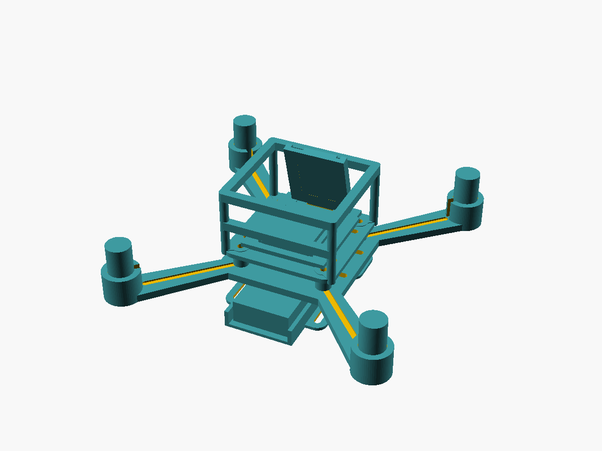
Frame geometry
- 123 mm diagonal Quad-X motor-center wheelbase
- motor centers at ±43.49 mm X/Y
- adjacent motor spacing about 87 mm
- 8520 brushed motors, nominal 8.5 mm body diameter
- 75/76 mm propellers
- shared 30 × 30 mm M2 stack
- battery mounted underneath for longitudinal CG adjustment
Printable stack
battery_sled_650_v2.stlframe_v2.stl- four 5 mm M2 spacers
electronics_deck_v2.stlflight_cage_v2.stlorcanopy_v2.stl
The XIAO camera mount faces forward. Keep the GY-91 close to the geometric center and aligned with the frame axes.
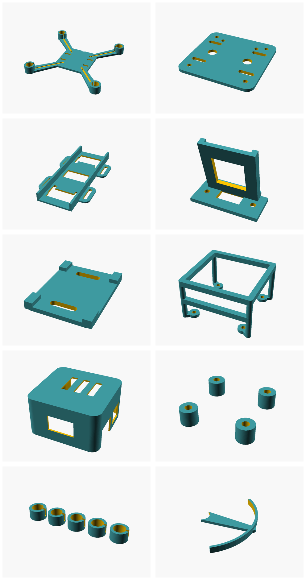
Part files
All current OpenSCAD sources and STL exports are in cad/airframe_v2/. Each printable part has a preview image in cad/airframe_v2/renders/ and is documented in the Airframe V2 README.
The shared parametric geometry is in cad/airframe_v2/scad/icedrone_v2_lib.scad; the small wrapper SCAD files render one selected part each.
8520 motor-cup calibration
Print motor_cup_test_v2.stl before the full frame. It contains 8.55 / 8.60 / 8.65 / 8.70 / 8.75 mm cup IDs. Use the smallest size that accepts the actual motor with a firm press fit without deforming the motor can or cracking the cup. Then adjust motor_id in icedrone_v2_lib.scad if required.
Battery and center of gravity
The default sled targets a 1S pack around 550–650 mAh and an envelope up to roughly 62 × 20 × 8 mm. Measure the delivered battery before the final print and slide it longitudinally until the assembled aircraft balances at the geometric center.
Kobra S1 print settings
| Part | Material | Layer | Walls | Infill | Support |
|---|---|---|---|---|---|
| Main frame | PETG | 0.16–0.20 mm | 4 | 100% | none |
| Electronics deck | PETG | 0.16–0.20 mm | 3–4 | 60–100% | none |
| Battery sled | PETG/TPU | 0.16–0.20 mm | 3 | 50–100% | none |
| XIAO mount | PETG/TPU 95A | 0.16–0.20 mm | 3 | 50–100% / 25–40% | normally none |
| IMU saddle | TPU 95A preferred | 0.20 mm | 3 | 20–35% | none |
| Flight cage | PETG | 0.16 mm | 3 | 100% | tree/build-plate support for top bridges only |
| Canopy | PETG | 0.16–0.20 mm | 3 | 60–100% | print roof-down; support as required |
Propeller CAD
Replacement/test propeller models are in cad/propellers/: standard 75 mm two-blade CW/CCW, experimental toroidal/low-noise CW/CCW, and a 1 mm shaft-fit coupon. The purchased molded propellers remain the preferred starting point.
Safety
Perform electrical, motor-order, motor-direction, IMU-orientation and failsafe tests without propellers installed. Fit propellers only after all prop-off checks pass. Use eye protection and restrain the aircraft for initial powered propeller tests.
← 02 - Electrical | Docs index | Next: 04 - Firmware →